FROM SLIDE RULES TO 3D RAYS: FIVE VINTAGE FACETING RULES AND WHAT LIGHT ACTUALLY DOES
A quick note: I’m not a trained gemologist. No GIA diploma, no mineralogy degree, and no traditional bench apprenticeship. Just a software engineer who fell down the rabbit hole of faceting machines, geometry, and how light bounces around inside crystals.
Flip through reprinted 1960s and 1970s lapidary manuals, browse old faceting-club binders, or listen to casual jewelry-counter sales talk, and you still run into a handful of pre-computer optical rules repeated as if they were strict laws of physics:
"Odd-sided stones like pentagons and heptagons leak light because there is no opposing facet across the middle to catch the bounce."
"Take a 43° quartz diagram, rescale the angles with the tangent-ratio formula so they sit above your mineral's critical angle, and the stone won't window."
"Look how brightly this loose sapphire lights up when I shine my pocket torch up through the culet!"
"One ideal proportion set maximizes white brilliance and rainbow fire at the exact same time."
To be fair right up front: gemologists, optical software pioneers, and experienced custom faceters retired every single one of those shortcuts decades ago. Starting in the late 1980s and 1990s with Richard W. Hughes's writing on windowing and extinction, Robert Strickland's GemCad and GemRay on desktop PCs, Garry Holloway's Ideal-Scope work, and GIA's 2001 to 2006 three-dimensional ray-tracing studies, the serious cutting community moved well beyond flat 2D rules of thumb.
Still, because classic mid-century books remain the first manuals handed to beginners (and retail counter folklore dies hard), newcomers keep bumping into these vintage rules without the historical context behind them. Every one of them started out as a clever, practical approximation invented by smart people working with slide rules and graph paper before 3D ray tracing existed:
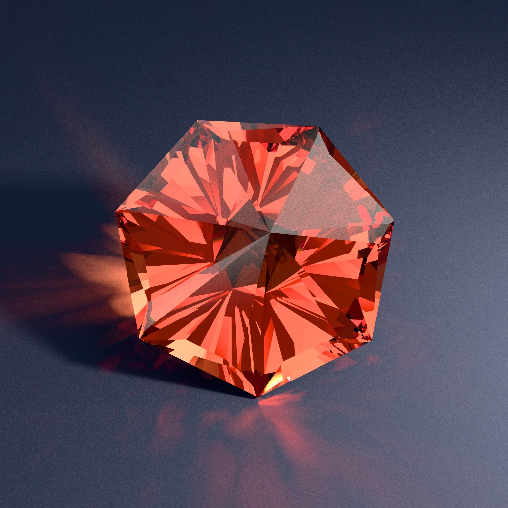
Here is where five of those classic faceting rules of thumb originally came from, why they made sense in the slide-rule era, and what three-dimensional crystal optics (plus real-world quirks like skin oil, two human eyes, and room lighting) actually do to light.
Old Rule 1: The 1919 2d Cross-section (and The "opposing Facet" Assumption)
This shortcut traces back to a genuine landmark: Marcel Tolkowsky's 1919 London monograph, Diamond Design: A Study of the Reflection and Refraction of Light in a Diamond. Tolkowsky was computing Snell's Law by hand, so to keep the trigonometry tractable without a computer, he sliced a round brilliant vertically through its center and traced meridian rays confined to a flat two-dimensional cross-section (arriving at his famous 40.75° pavilion, 34.5° crown, and 53% table baseline).
In that 2D cross-section, a ray enters the crown, hits Pavilion Facet A on the left, travels straight across the center to an opposing Pavilion Facet B sitting 180° away on the right, and exits back toward your eye.
It was admirable 1919 engineering, and later popularizers over-generalized the drawing into a rule Tolkowsky himself never intended for fancy shapes: the idea that every pavilion facet needs an opposing 180° mirror partner across the center, or light will spill out the back. Under a flat 2D mental model, odd-numbered symmetries like 3-fold trillions, 5-fold pentagons, and 7-fold heptagons looked suspicious, since every flat wall faces a sharp corner directly across the culet.
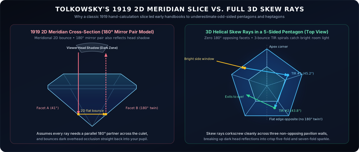
Once Robert Strickland's GemRay put 3D desktop ray tracing into custom cutters' hands in the 1990s (championed at the bench by designers like Jeff Graham), and Ilene Reinitz, Mary Johnson, Thomas Moses, and the GIA cut-grading team published their 2001 Gems & Gemology series ("Modeling the Appearance of the Round Brilliant Cut Diamond") alongside Garry Holloway's research, the limitation of 2D slices was quantified in full. Flat meridian rays account for only a tiny slice of the hemisphere of light entering a gem. Most rays enter off-axis and travel as 3D skew rays, corkscrewing around adjacent pavilion walls in helical paths before returning out the crown.
Breaking 180° opposing mirror pairs also breaks up observer head shadow. Lean over an even-symmetry stone and your own head blocks a 20° to 30° cone overhead; 180° retroreflectors can bounce that dark silhouette back in broad blocks, whereas odd-fold symmetries scatter it into lively three-, five-, and seven-fold kaleidoscopes:
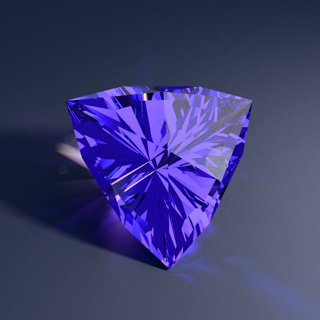
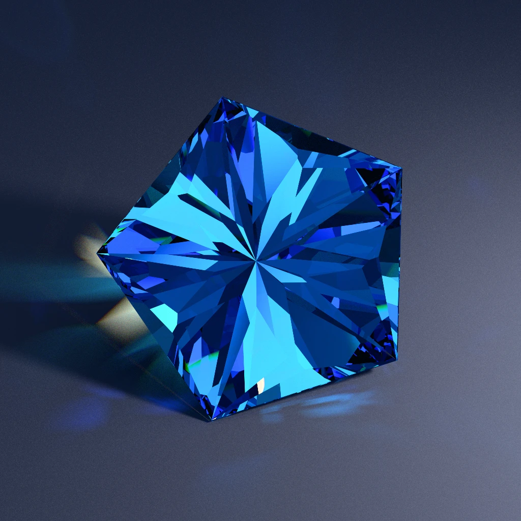
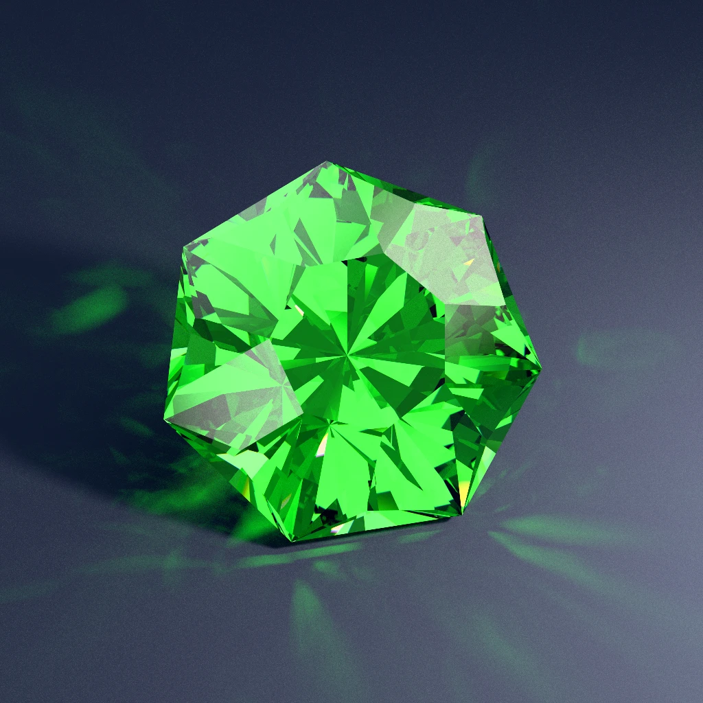
So why are pentagons and heptagons still uncommon in commercial jewelry cases? One practical reason is rough crystal habit: elongated tourmaline and beryl crystals naturally yield better weight as ovals or emerald cuts than as equant polygons. For equant rough like garnet, spinel, sapphire nodules, quartz, and lab crystals, though, the bottleneck was mostly factory hardware:
- The standard 96-tooth index gear:
96divides cleanly by3,4,6,8,12, and16, whereas96 / 5 = 19.2and96 / 7 = 13.714. Cutting a pentagon or heptagon required swapping in an80,120, or84gear wheel. - Pre-cast commercial mountings: Wholesale findings catalogs stock thousands of stamped
4-prongand6-prongheads built for parallel setting pliers across180°opposing prongs, and very few pre-made5-prongor7-prongbaskets.
Old Rule 2: Single-bounce Critical-angle Charts And Tangent-ratio Scaling
Open John Sinkankas's Gem Cutting: A Lapidary's Manual (1962) or Glenn and Martha Vargas's Faceting for Amateurs (1969), and you find two workhorse tools taught in every mid-century lapidary club: first, a mineral critical-angle table (40.5° for Quartz at RI 1.54, 34.6° for Sapphire at RI 1.76, 24.4° for Diamond at RI 2.42) paired with the advice to cut pavilion mains "2° to 3° above the critical angle" (like the classic 43° quartz pavilion); and second, the Tangent Ratio Method, which rescales a diagram from one refractive index to another by multiplying angle tangents.
Before personal computers, those two rules saved thousands of cutters from ruining rough. Three-dimensional ray tracing and everyday jewelry wear later exposed three blind spots that a 1D angle table cannot catch:
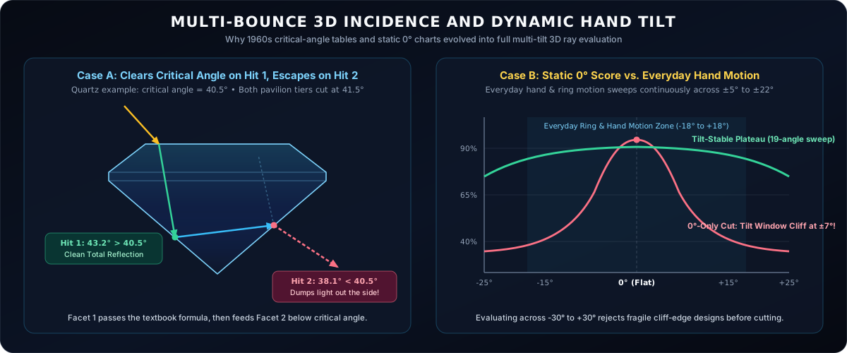
- Multi-Bounce 3D Incidence: Snell's critical angle applies to the local 3D angle between the incoming ray and the facet normal on each individual bounce, not to the mast dial angle relative to the girdle plane. An off-axis ray in quartz can strike Pavilion Facet 1 at
43.2°(reflecting cleanly), then ricochet across a compound tier junction onto Pavilion Facet 2 at38.1°and exit out the side. Tangent-ratio scaling preserves a cut's physical depth ratio and meetpoints, not its multi-bounce 3D ray confinement. - Dynamic Hand Tilt (Why
0°-Only Scores Mislead): Early computer brightness tables often ranked designs at a single dead-flat0°viewing angle. On a finger or pendant, a gemstone rocks continuously across5°to25°(a major reason the 2006 GIA Cut Grading System evaluated appearance across a range of viewing geometries). A pavilion perched half a degree above its critical-angle cliff can post a huge0°brightness number and open a tilt window the moment your hand moves7°. - The "Dirty Ring" Skin-Oil Shift: Almost every ray tracer (ours included!) models clean dry air (
n = 1.00) behind the pavilion. Wear a ring for two days, however, and hand lotion, soap film, and skin oils (n ≈ 1.47) coat the back facets. Because the critical angle equalsarcsin(n_outside / n_gem), wetting the pavilion with skin oil pushes quartz's critical angle from40.5°all the way to72.6°, and sapphire's from34.6°to56.6°, causing both to window where oil touches until scrubbed with warm soapy water. By contrast, diamond's high2.42refractive index keeps its oiled critical angle down at37.4°, which a40.8°pavilion still clears comfortably even when dirty.
Old Rule 3: Treating All Darkness As Leakage (and The Bottom-penlight Habit)
In his classic 1988 Gemological Digest paper, "Brilliance, Windows and Extinction in Gemstones" (later expanded in Ruby & Sapphire), gemologist Richard W. Hughes laid out the anatomy of commercial weight-saving cuts: overly shallow culet zones that open a see-through window in the center, paired with overly steep zones darkened by extinction. (Hughes also noted a fair real-world exception that uniform computer models miss: in Sri Lankan sapphire rough where all the blue sits in a thin 1 mm color spot near the tip, traditional cutters sometimes used odd pavilion depths on purpose just to park that tiny blue zone right at the culet apex so it colored the whole face-up gem.)
When early automated optimizers tried to penalize windowing on a computer, many used a blunt shortcut: shoot light into the crown, sum what came back, and label everything dark as "leakage." Modern optical analysis separates four very different physical events:
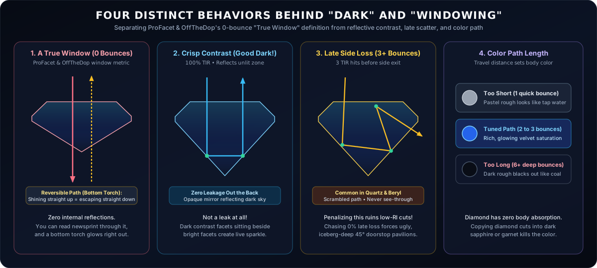
- A True Window (
0internal bounces): Light enters the crown, strikes its very first pavilion facet below the critical angle, and transmits straight out the back with zero internal reflections, letting you read newsprint or see skin right through the middle of the gem. This exact zero-bounce definition, "A True Window," is what both ProFacet and OffTheDop use to measure and penalize windowing. By tracking the internal bounce count of every ray across tilt angles, our scorer catches genuine see-through holes without punishing reflective contrast or harmless late scatter. - Structured Contrast (Good Darkness) and Two Human Eyes: As the AGS ASET framework and GIA's scintillation studies established decades ago, a stone surrounded by uniform diffused light looks flat and lifeless. When a facet undergoes 100% Total Internal Reflection twice across the pavilion and aims back toward your dark pupil or head cone, it creates crisp dark contrast right beside bright neighboring facets. Better yet, humans inspect gems with two eyes spaced roughly
63 mmapart (4°to6°angular separation at arm's length): a facet reflecting dark pupil contrast to your left eye can simultaneously flash a bright lamp to your right eye, producing stereoscopic luster and live scintillation that single-lens camera renders can only hint at. - Late Multi-Bounce Side Scatter (
3+bounces): In lower-RI minerals like Quartz (1.54) and Beryl (1.58), some oblique rays bounce three times via total internal reflection and escape near the girdle on the fourth hit. Because the image has already folded three times, you cannot see through the stone. Penalizing third-bounce scatter as if it were a zero-bounce True Window pushes naive optimizers into overly steep45°+quartz pavilions. - The Bottom-Penlight Habit (Reversible Ray Paths): Pocket torches are indispensable for checking inclusions, silk, and color zoning in rough and loose parcels. Still, across gem markets and retail counters you occasionally see someone hold a penlight underneath the culet of a loose stone to show off how brightly the table glows from below. By Helmholtz reciprocity, optical ray paths work identically in reverse: any zero-bounce channel that lets a torch beam shoot straight up through the culet out the table is the exact same True Window that lets overhead room light escape straight out the bottom once the stone is set.
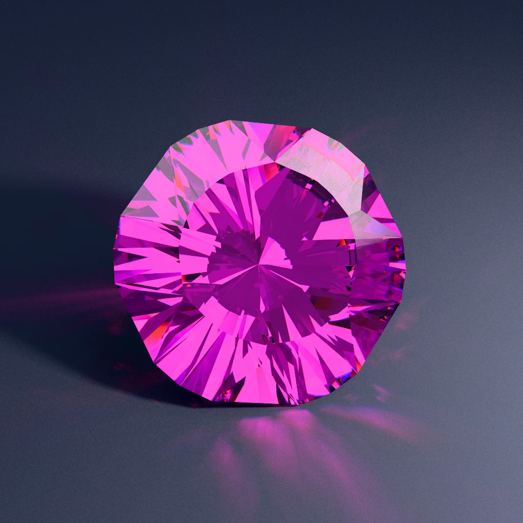
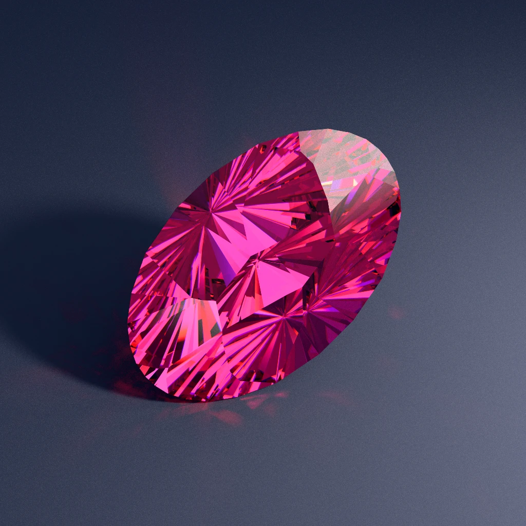
You can see how intentional, 100%-reflective dark contrast zones frame bright facets (and tame oval bow-ties) in these two Signature Collection cuts:
Old Rule 4: Expecting One "ideal" Cut To Fit Every Mineral, Crown, And Room Light
Early retail brochures loved the word "Ideal," which left many buyers assuming that a single magic proportion set works across different minerals, or maximizes white brilliance and rainbow fire at the same time.
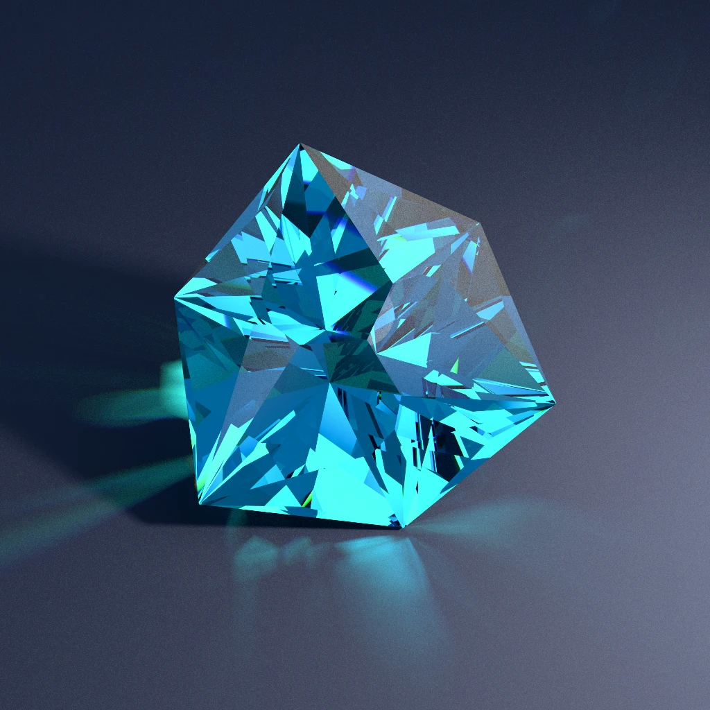
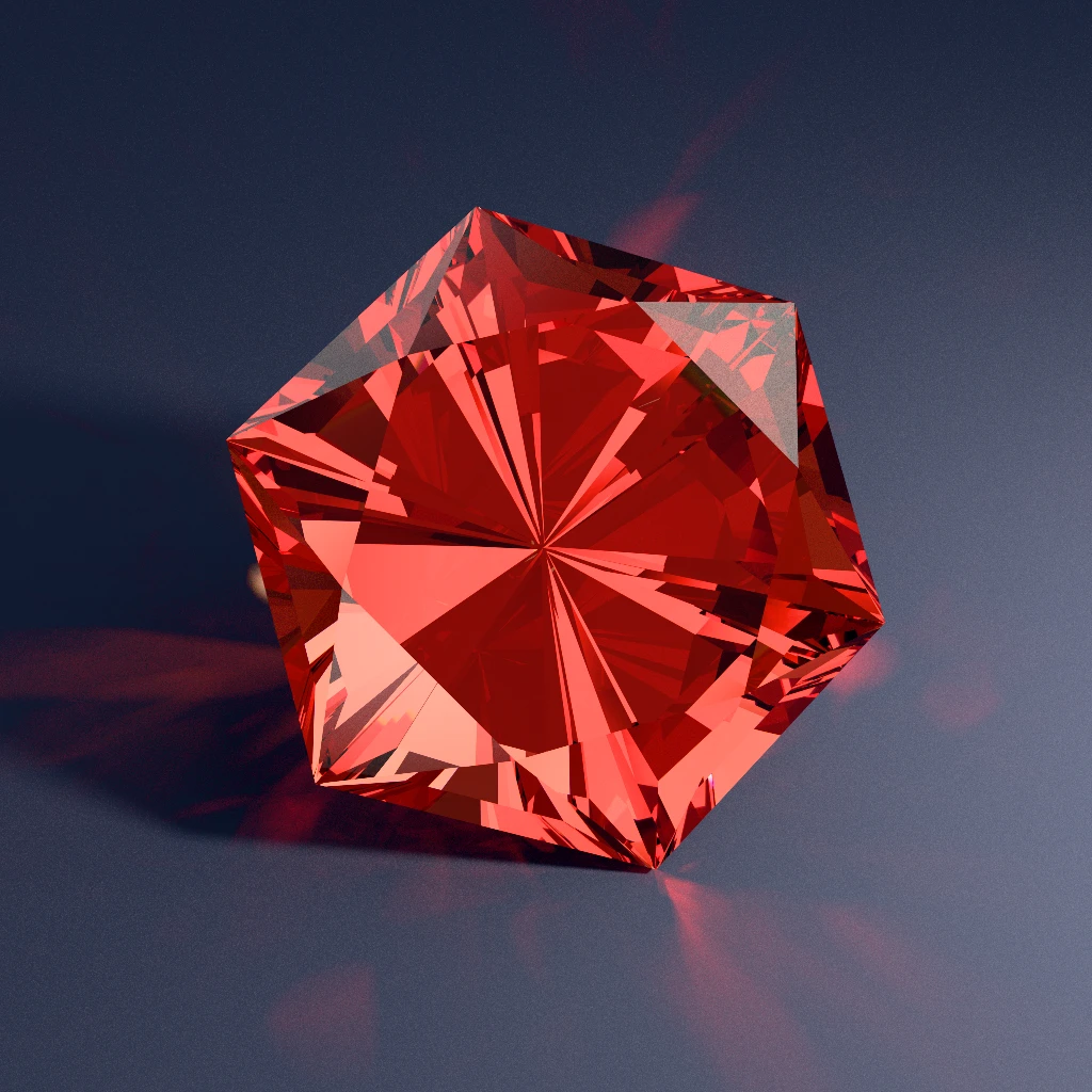
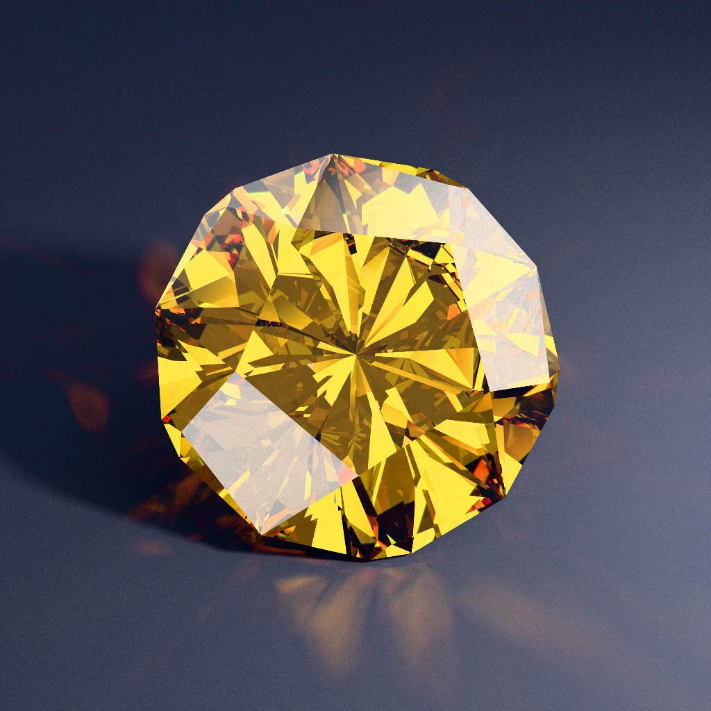
Mineral physics rules out universal proportions immediately. Moving from Quartz (RI 1.54, critical angle 40.5°) to Corundum (RI 1.76, critical angle 34.6°) to Moissanite (RI 2.67, critical angle 22.0°) nearly doubles the internal cone of Total Internal Reflection. Meanwhile, colored gems develop face-up saturation through Beer-Lambert absorption along every millimeter a photon travels inside the crystal. Even within the same species (RI 1.76 sapphire), pale pastel rough benefits from slightly longer multi-bounce optical paths to deepen color, whereas dark basaltic rough cut too deep drinks up too much light and goes inky. Each refractive index regime thrives on different geometry:
Even inside a single colorless, high-dispersion crystal, white brilliance and rainbow fire pull crown angles in opposite directions. In Fall 2001, GIA researchers published "Modeling the Appearance of the Round Brilliant Cut Diamond: An Analysis of Fire, and More About Brilliance" in Gems & Gemology, mapping white light return and dispersed fire across tens of thousands of 3D proportion combinations and proving that their peaks do not coincide.
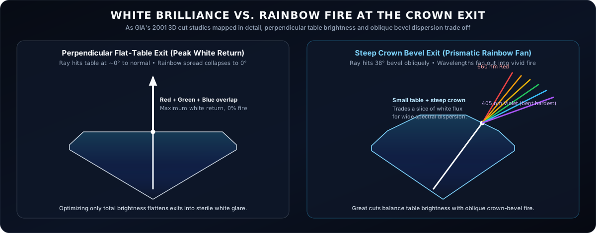
When an internal ray exits nearly perpendicular through a wide flat table, red and violet barely diverge, delivering high white brilliance with minimal color spread. Tilting outgoing rays through smaller tables and angled crown bevels bends violet harder than red and fans wavelengths into spectral fire (up until over-steep crown angles trigger internal crown Total Internal Reflection).
Room lighting and human eye resolution complete the picture. Under a diffuse overcast sky or wide fluorescent shop tubes, light enters from every angle at once, so dispersed red and blue beams from neighboring directions overlap and recombine back into white light. Seeing vivid fire requires small, high-contrast point lights (sunlight, track spotlights, candle flames) plus crown facets wide enough for human visual acuity (1 to 2 arcminutes at arm's length) to resolve individual colored flashes instead of blending tiny pinpricks together. Compare two colorless RI 2.67 Extended Showcase cuts rendered under the exact same studio spotlights with full spectral dispersion enabled:
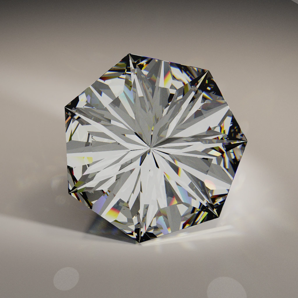
100% flat table, full spectral dispersion enabled). Because central rays exit nearly perpendicular to the broad flat top, red, green, and blue stay stacked as crisp silver-white brilliance (1.09 brightness) with fire confined to the rim.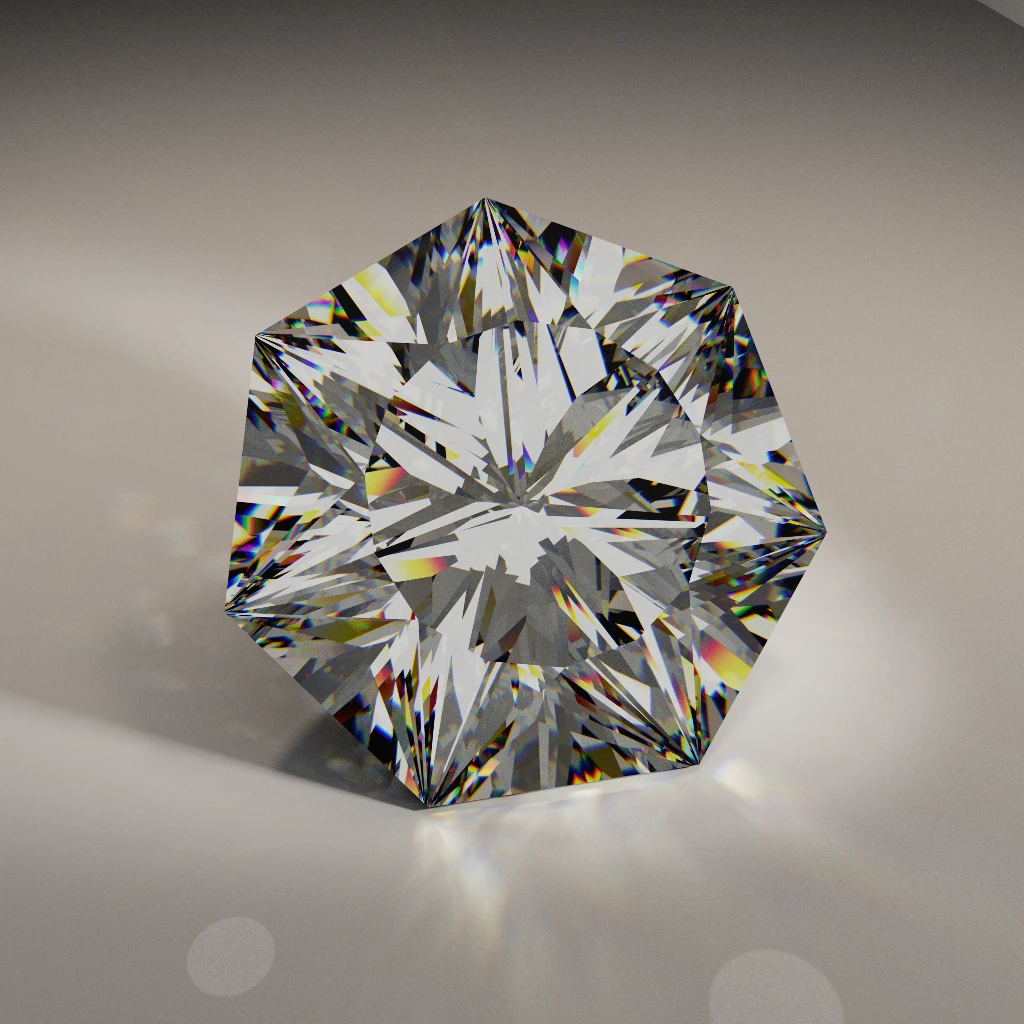
30% table with 21 angled crown bevels, identical studio lights and dispersion). Trading flat table area for angled crown bevels splits the exact same colorless crystal into vivid red, emerald, cobalt, and violet fire.Old Rule 5: Counting On 0.1° Dial Precision To Rescue A Weak Diagram (and Where Crystals Still Humble Software)
In United States Faceters Guild (USFG) and Australian Faceters Guild competitions, judges inspect stones under 10× magnification and deduct points for microscopic meetpoint misses, polish scratches, and girdle variations. At the bench, 0.1° angle repeatability genuinely matters for clean meetpoint closure (because small drift on Tier 1 cascades down a multi-tier meetpoint chain) and keeps radial star patterns winking symmetrically, much like GIA's 2005 to 2006 "Painting and Digging Out" studies documented in diamond cutting.
The trap for newcomers is confusing execution precision with underlying optical design, worrying over 0.1° on an encoder readout while cutting an unvetted vintage chart that opens a 35% True Window at 8° of hand tilt. When we run 100-trial Monte Carlo "Cut Forgiveness" sweeps across our catalog, randomly perturbing tier angles to mimic real bench drift, designs perched on a broad 3D optical plateau keep over 98% of their integrated light performance, comfortably outperforming a 0.01°-accurate execution of a tilt-fragile diagram.
At the same time, we should never replace old slide-rule shortcuts with blind faith in software. One place where natural crystals still humble ray tracers (including ours!) is pleochroism and closed optic axes.
Cubic minerals like diamond, spinel, and garnet treat light identically in every crystal direction. Uniaxial and biaxial colored gems (tourmaline, corundum, beryl, quartz, zircon, tanzanite) do not. While our bidirectional path tracer models uniaxial double-refraction facet doubling in stones like zircon and moissanite, our fast evolutionary angle-finder still models color absorption isotropically, as if the crystal were uniformly tinted optical glass.
Consider a classic dark green trigonal tourmaline with a "closed c-axis" (a familiar challenge in Lotus Gemology and USFG preforming guides, and the reason specialized bar cuts like Michiko Huynh's Beginner Tourm exist). View the tourmaline prism across its side (a/b axes) and it glows rich emerald green; look straight down the length of the pencil (c-axis) and the crystal absorbs nearly 100% of the ordinary ray like black electrical tape. Orient a round table perpendicular to that closed c-axis and any isotropic ray tracer will predict a high-scoring gem, right before the real stone comes off your dop pitch black. Reading a dichroscope and orienting rough on the dop still belongs squarely to human eyes at the bench.
Putting 3d Optics To Work At Your Bench
Looking back from century-old 2D drawings to modern 3D path tracing leaves three practical takeaways for everyday cutting:
- Odd symmetries thrive on equant rough: Three-, five-, and seven-fold designs lock light cleanly via 3D skew rays and break up dark head shadow without needing
180°opposing facets. - Multi-tilt testing (and clean pavilions) beat single-angle charts: Checking full 3D ray paths across
0°to25°catches second-bounce escapes and0°tilt cliffs before you touch rough to a lap, and a quick toothbrush scrub keeps skin oil from shifting your critical angle during wear. - "A True Window" (
0bounces) is distinct from dark contrast: Separating zero-bounce transparency (the True Window metric used by ProFacet and OffTheDop) from100%-TIR dark contrast lets quartz, beryl, sapphire, and high-dispersion crystals each get geometry tailored to their own physics and lighting.
Want to test a diagram you already own across -30° to +30° of live tilt, toggle spectral dispersion under spotlights, or inspect our Signature Collection and Extended Showcase cuts in 3D? Drop any .fsl or .gem file into ProFacet.com, or browse the catalog on OffTheDop:
Explore Tilt-Tested Cuts & Odd-Symmetry Polygons
Every diagram in our catalog is scored across full 3D tilt sweeps to eliminate zero-bounce True Windows, with GPU BDPT renders, ASET maps, and interactive 3D inspection in ProFacet.
Sources & Further Reading
- Marcel Tolkowsky (1919): Diamond Design: A Study of the Reflection and Refraction of Light in a Diamond (E. & F.N. Spon, London). The original 2D meridian-plane derivation of the
40.75°pavilion /34.5°crown round brilliant baseline. - John Sinkankas (1962) / Glenn & Martha Vargas (1969): Gem Cutting: A Lapidary's Manual and Faceting for Amateurs. Classic mineral critical-angle tables and the 1D Tangent Ratio angle-rescaling method.
- Richard W. Hughes (1988, 1997, 2017): "Brilliance, Windows and Extinction in Gemstones" (Gemological Digest, Vol. 2, No. 1) and Ruby & Sapphire: A Gemologist's Guide (Lotus Publishing). Definitive analysis of windowing, extinction, color-zoned rough orientation, pleochroism, and field torch inspection.
- Robert W. Strickland (1989–2005): GemCad and GemRay 3D faceting CAD and desktop ray-tracing software, which enabled custom cutters such as Jeff Graham to test odd-symmetry and non-round designs in 3D.
- Ilene M. Reinitz, Mary L. Johnson, Thomas M. Moses et al. (2001): "Modeling the Appearance of the Round Brilliant Cut Diamond: An Analysis of Brilliance" (Summer 2001) and "An Analysis of Fire, and More About Brilliance" (Fall 2001), Gems & Gemology, Vol. 37, GIA. Full 3D hemispherical ray-tracing analysis of skew rays, lighting geometry, and the brilliance-versus-fire crown tradeoff.
- Thomas M. Moses, Matthew Hall, Ilene M. Reinitz et al. (2004–2006): "A Foundation for Grading the Overall Cut Quality of Round Brilliant Diamonds" and GIA's Painting and Digging Out studies, Gems & Gemology, GIA.
- United States Faceters Guild (USFG): Competition Judging Criteria (
10×meetpoint, symmetry, and polish scoring) and closedc-axisuniaxial tourmaline orientation guides.